

If you have ever looked at a pressure gauge and wondered how a spring, a tube, or a flexible diaphragm can tell you exactly how much force a fluid is exerting inside a pipe or a vessel, you are not alone. The pressure gauge working principle is one of those technologies so reliable and so well-engineered that it has been in continuous industrial use for over 150 years — with the same fundamental physics working in a 1-inch Bourdon tube gauge in a laboratory and a 12-inch diaphragm gauge on a chemical plant header. Understanding the pressure gauge working principle is not just an academic exercise — it is what allows engineers, maintenance technicians, and procurement specialists to specify the right gauge for the right application, interpret readings correctly, and troubleshoot measurement errors when they occur. This article explains the pressure gauge working principle for every major gauge type in common industrial use.
The Fundamental Physics of Pressure Gauge Working Principle
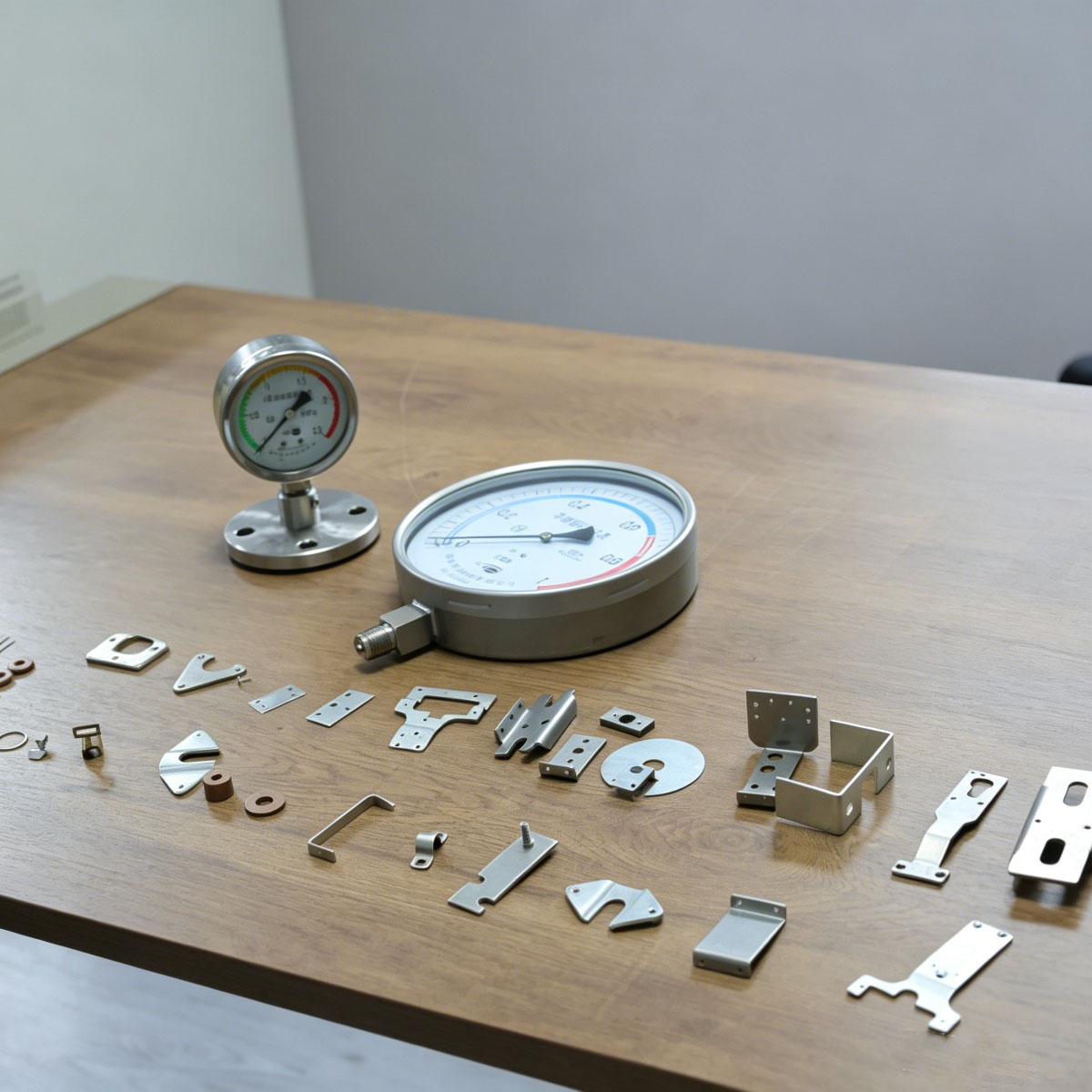
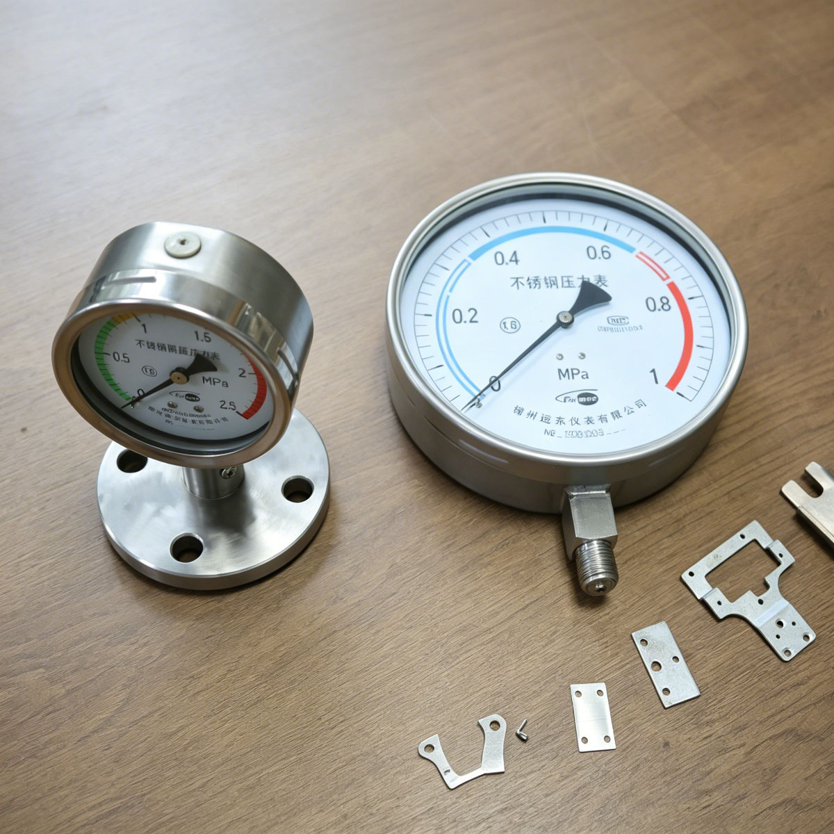
Before examining specific mechanisms, it helps to understand what pressure actually is and what the pressure gauge working principle must accomplish. Pressure is force per unit area — typically measured in pounds per square inch (psi) in US practice or bar/ Pascal in SI-based systems. A pressure gauge does not measure force directly. It measures the deformation of an elastic element — a tube, a diaphragm, or a piston — that deforms in response to the fluid pressure applied to it, then converts that deformation into proportional pointer rotation on a calibrated dial. The pressure gauge working principle is, at its core, a problem in applied mechanics: how much does an elastic element deform under a known pressure, and how reliably can that deformation be converted into a readable output?
Absolute vs. Gauge vs. Differential Pressure
The pressure gauge working principle must also account for the reference pressure against which the measurement is taken. A gauge pressure instrument measures pressure relative to ambient atmospheric pressure (approximately 14.7 psi at sea level). A compound gauge measures both positive gauge pressure and vacuum. An absolute pressure instrument measures relative to a perfect vacuum — including the 14.7 psi atmospheric pressure as part of the reading. A differential pressure gauge measures the pressure difference between two points in a system, which is critical for flow measurement, filter monitoring, and level measurement applications. Understanding which reference frame a pressure gauge working principle operates in matters enormously for correct installation and correct reading interpretation.
Bourdon Tube Pressure Gauge Working Principle
The Bourdon tube is the most widely used pressure gauge working principle in industrial applications, found in everything from hydraulic test benches to natural gas distribution lines. The mechanism consists of a thin-walled, C-shaped or helical tube sealed at one end and open at the other to the process pressure. The open end is fixed to the gauge body and connected to the process connection. When pressure increases inside the tube, the tube tends to straighten — the C-shape opens slightly — because the pressurized inner surface of the tube experiences more force than the outer surface. This elastic deformation is transmitted through a linkage to a pointer shaft, which rotates against a calibrated dial.
The pressure gauge working principle of the Bourdon tube is a classic application of the principle of elastic deformation: the tube's cross-sectional geometry determines how much displacement occurs per unit of pressure increase. A C-shaped Bourdon tube with a flat elliptical cross-section produces a deflection of approximately 0.001 to 0.005 inches per psi of applied pressure. A helical Bourdon tube — multiple turns wound into a coil — produces much larger deflection for the same pressure range, which is why helical tubes are used in gauges with lower pressure ranges where higher sensitivity is required. The pressure gauge working principle using Bourdon tubes achieves accuracy of ±0.25 to ±2.0 percent of full scale depending on the gauge class.
Material Selection in Bourdon Tube Pressure Gauge Working Principle
The pressure gauge working principle is sensitive to the material of the Bourdon tube because the tube must be elastic — it must return to its original shape when pressure is removed — without yielding or permanently deforming over years of cyclic loading. Copper alloys (phosphor bronze, brass) are used for Bourdon tubes in low-pressure gauges (below 1,000 psi) and non-corrosive service. Stainless steel 316L is specified for corrosive media, high-pressure applications, and process conditions where copper alloy is incompatible with the process fluid. For oxygen service, oil-free Bourdon tube gauges use specially cleaned stainless steel to prevent combustion risk from hydrocarbon residue. The pressure gauge working principle depends on the tube material remaining chemically stable in the process environment — corrosion that thins the tube wall changes the elastic response and produces measurement drift or tube failure.
Diaphragm Pressure Gauge Working Principle
The diaphragm pressure gauge working principle uses a flexible circular disc — a diaphragm — as the pressure-sensing element instead of a tube. Process pressure acts on one side of the diaphragm, deflecting it against the force of a calibrated spring or against the elastic resistance of the diaphragm itself. The deflection is measured by a linkage connected to a pointer, similar to the Bourdon tube mechanism. The diaphragm pressure gauge working principle is particularly suited to low-pressure measurement (from vacuum to 200 psi), to applications with pulsating pressure that would fatigue a Bourdon tube, and to applications where the process media might clog a small Bourdon tube port.
The sensitivity of the diaphragm pressure gauge working principle is determined by the diaphragm diameter, thickness, and the number of convolutions (for corrugated diaphragms). A larger, thinner diaphragm with more corrugations produces greater deflection per unit of pressure — increasing sensitivity for low-pressure ranges. For very low pressures — below 10 inches of water column — a diaphragm capsule (two diaphragms sealed at their perimeters, forming a small sealed volume) amplifies the deflection further. This diaphragm capsule pressure gauge working principle is the standard mechanism in differential pressure transmitters, barometers, and low-range pressure instruments.
Diaphragm Seals in Pressure Gauge Applications
A critical extension of the diaphragm pressure gauge working principle is the diaphragm seal — a flexible element that isolates the gauge mechanism from the process fluid. The diaphragm seal consists of a thin metal diaphragm (typically 316L stainless or Hastelloy) welded to a seal body that connects to the process piping. The space between the diaphragm and the gauge is filled with a fill fluid (silicone oil, fluorinated oil for oxygen or food service, or glycerin for high-vibration applications). The pressure gauge working principle operates normally — the fill fluid transmits pressure from the process to the gauge mechanism — while the diaphragm provides a contamination barrier. Diaphragm seals are essential for pressure gauge working principle applications with corrosive,粘性, or particulate-laden media that would damage a standard gauge mechanism.
Piston Pressure Gauge Working Principle
The piston pressure gauge working principle — also called a deadweight tester when used as a calibration standard — uses a precisely machined piston and cylinder assembly where process pressure acts on the piston face to balance against a known weight mass. In a reference-grade deadweight tester, calibrated weights are placed on the piston, and the pressure required to lift the piston against gravity is the known reference pressure. In a piston-type pressure gauge, the pressure gauge working principle uses a spring-loaded piston that deflects against the process pressure, with the deflection converted to pointer rotation. The piston pressure gauge working principle provides the highest accuracy of any mechanical gauge type — typically ±0.05 to ±0.25 percent of reading — and is used as the primary calibration standard for pressure instruments.
Applications Suited to Piston Pressure Gauge Working Principle
The piston pressure gauge working principle is typically found in calibration laboratories, hydraulic test systems, and high-pressure applications above 10,000 psi where its superior accuracy and durability outweigh its larger size and higher cost. In hydraulic power systems, hydraulic test gauges with piston mechanisms handle pressure spikes and cycling better than Bourdon tubes at very high pressures. The pressure gauge working principle in piston gauges is less sensitive to vibration than Bourdon tubes because the piston mechanism is inherently more rigid — though the sliding friction of the piston seal introduces hysteresis that must be accounted for in high-precision applications.
Accuracy, Hysteresis, and Temperature Effects on Pressure Gauge Working Principle
The pressure gauge working principle of any elastic element-based instrument is affected by three factors that limit its accuracy: hysteresis, temperature, and fatigue. Hysteresis is the difference in reading between the same pressure applied while increasing versus decreasing — caused by friction in the linkage and elastic energy storage in the sensing element. The pressure gauge working principle for Bourdon tube gauges typically specifies hysteresis within 0.1 to 0.5 percent of full scale, depending on the gauge class. Temperature affects the pressure gauge working principle because both the spring constant of the sensing element and the dimensions of the pressure chamber change with temperature. A temperature increase of 20°F above the reference temperature (usually 68°F) can produce an additional error of 0.3 to 1.0 percent of full scale in an uncompensated gauge.
Gauge Class and Accuracy Specifications
The pressure gauge working principle accuracy is specified as a gauge class — a percentage of full scale — in accordance with EN 837-1 (European) or ASME B40.100 (North American) standards. A Class 1.0 gauge (EN 837-1) has an accuracy of ±1.0 percent of full scale across the entire dial range. A Class 0.25 gauge has accuracy of ±0.25 percent of full scale. The pressure gauge working principle accuracy class applies across the full scale — meaning a 100 psi gauge with Class 1.0 accuracy has a maximum error of ±1.0 psi at any point on the dial, including at 10 psi where the relative error (10 percent) is much larger than the stated class would suggest. This is why selecting a gauge with a range appropriate to the measurement — ideally operating between 25 and 75 percent of full scale — is critical to achieving the accuracy the pressure gauge working principle is rated for.
Installation Effects on Pressure Gauge Working Principle
The pressure gauge working principle does not operate in isolation — it is affected by how and where it is installed in the process system. A pressure gauge installed directly at a pump discharge experiences full pump pulsation — a rapid oscillation in pressure that fatigues the Bourdon tube and causes pointer flutter and premature mechanism wear. A pressure gauge installed with a pigtail siphon (a coiled pipe filled with process liquid) absorbs pulsation by creating a liquid column that dampens pressure fluctuations before they reach the gauge mechanism. For steam service, a pigtail siphon also prevents live steam from reaching the gauge and overheating the Bourdon tube. The pressure gauge working principle performs reliably only when the installation protects the mechanism from excessive pulsation, temperature, and vibration.
Reading Accuracy and Point-of-Use Considerations
Even a perfectly calibrated pressure gauge with a flawless pressure gauge working principle can give a misleading reading if it is installed at a height different from the point where the pressure is actually being measured. In static fluid systems, hydrostatic head — the pressure difference created by the weight of the fluid column between the measurement point and the gauge — can add or subtract from the reading. In a vertical pipe, the elevation difference between the gauge connection and the centerline of the pipe where the pressure exists may introduce a measurable error if the specific gravity of the process fluid is high. For water systems, every foot of elevation difference changes the reading by approximately 0.433 psi. The pressure gauge working principle itself is accurate — but the reading must be interpreted correctly relative to the system geometry.
Conclusion
The pressure gauge working principle converts fluid pressure into mechanical displacement through three primary mechanisms — the Bourdon tube, the diaphragm, and the piston — each suited to different pressure ranges, media conditions, and accuracy requirements. Understanding the pressure gauge working principle in detail helps engineers and technicians select the right gauge type, specify the correct materials and accuracy class, install it with appropriate pulsation and temperature protection, and interpret readings correctly relative to the process conditions. Whether the application is hydraulic system monitoring, chemical process control, or HVAC system balancing, the pressure gauge working principle provides reliable, well-characterized pressure measurement when the right instrument is selected for the right service. For precision metal stamping parts buyers sourcing pressure gauge components, the pressure gauge working principle informs what tolerances and material specifications to require from a precision fabrication supplier — Bourdon tube blanks, diaphragm discs, and seal housings all depend on precision stamping to achieve the dimensional control that the pressure gauge working principle requires.
FAQ
What is the most common pressure gauge working principle?
The Bourdon tube is the most widely used pressure gauge working principle, where process pressure causes a C-shaped or helical tube to elastically straighten, converting pressure into pointer rotation on a calibrated dial.
How accurate is a Bourdon tube pressure gauge working principle?
Bourdon tube gauge accuracy typically ranges from ±0.25 to ±2.0 percent of full scale depending on the gauge class. The accuracy class applies to the full scale, so the measurement should be made between 25 and 75 percent of full scale for best accuracy.
When is a diaphragm pressure gauge preferred over a Bourdon tube?
A diaphragm pressure gauge working principle is preferred for low-pressure ranges (below 200 psi), pulsating service, and applications with corrosive,粘性, or particulate-laden media that would damage a Bourdon tube mechanism.
What causes a pressure gauge to give inaccurate readings?
The pressure gauge working principle accuracy is affected by hysteresis from linkage friction, temperature changes that alter elastic modulus and dimensions, fatigue from excessive pressure cycling, and installation effects including pulsation, vibration, and elevation head differences.
References
1. EN 837-1:1996, "Pressure Gauges — Part 1: Bourdon Tube Pressure Gauges," European Committee for Standardization, Brussels, 1996.
2. ASME B40.100-2013, "Pressure Gauges and Gauge Attachments," American Society of Mechanical Engineers, New York, 2013.
3. Doebelin, E.O. and Manik, D.N., "Measurement Systems: Application and Design," 6th Edition, McGraw-Hill, New York, 2007.
4. Holman, J.P., "Experimental Methods for Engineers," 8th Edition, McGraw-Hill, New York, 2011.
5. ASHRAE Handbook — Fundamentals, American Society of Heating, Refrigerating and Air-Conditioning Engineers, Atlanta, 2021.