

Tolerance is where the difference between a general fabrication shop and a precision sheet metal fabrication operation becomes unmistakable. A general precision sheet metal fabrication shop produces parts with dimensional tolerances of ±0.030 to ±0.060 inches—adequate for many industrial enclosures and structural components. A precision sheet metal fabrication shop delivers tolerances of ±0.005 to ±0.015 inches on features that other shops consider difficult to measure consistently. This article explains how precision sheet metal fabrication actually achieves that level of control and what buyers need to know to specify and verify it.
What Defines Precision in Precision Sheet Metal Fabrication
Precision sheet metal fabrication is defined not by the equipment alone but by the combination of machine capability, operator skill, measurement systems, and process control that together produce consistently tight dimensions. The machine tool—CNC press brake, laser cutting system, forming equipment—sets the theoretical capability boundary. The operator's understanding of springback compensation, setup repeatability, and in-process measurement closes the gap between theoretical and actual. The measurement system—CMM, laser scanner, precision gauge—verifies that the process stayed in control. And the process control documents whether it did. All four elements must be present for precision sheet metal fabrication to deliver on its name.
The Springback Challenge in Precision Sheet Metal Fabrication
Springback is the enemy of precision in precision sheet metal fabrication. When sheet material is bent around a die, it elastic recovery when the press unloads, opening the bend angle slightly. The amount of springback depends on the material's yield strength, thickness, the die width-to-thickness ratio, and the bend angle itself. A 90-degree bend in 0.090-inch 5052-H32 aluminum springs back 1 to 3 degrees. The same bend in 0.090-inch 304 stainless springs back 4 to 7 degrees. For precision sheet metal fabrication to hit ±0.5 degrees on a 90-degree bend, the operator must know the exact springback compensation for that specific material lot, thickness, and tooling combination—and the measurement system must resolve angular differences of 0.1 degrees to verify the result.

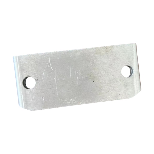
Tooling Technology for Precision Sheet Metal Fabrication
The tooling in a precision sheet metal fabrication operation differs from general fabrication in material selection, precision of manufacture, and maintenance frequency. Air-bending on a CNC press brake—the most common precision sheet metal fabrication forming method—requires precision-ground V-dies with width tolerances of ±0.001 inches and punch noses with radii held to ±0.0005 inches. Worn V-dies with ±0.005 inch width variation produce measurable variation in bend angle across the part, which is unacceptable in precision sheet metal fabrication. A precision sheet metal fabrication shop maintains its tooling to measurement instrument standards, re-grinding and re-certifying dies at defined intervals rather than waiting for visible wear to trigger replacement.
Segmented versus Monoblock Dies in Precision Sheet Metal Fabrication
For precision sheet metal fabrication of parts with bends in multiple directions—common in enclosures, brackets, and structural frames—the choice between segmented and monoblock press brake dies affects achievable accuracy. Segmented dies, which split the die opening into separate segments to allow partial insertion into flanged areas, introduce a seam between segments that creates a subtle but measurable seam mark on the outside of the bend. For cosmetic precision sheet metal fabrication parts, this seam mark is visible in the bend radius. For structural precision sheet metal fabrication, the seam mark is a stress concentration point that can affect fatigue performance. Monoblock dies—machined from solid steel bar stock with no seams—eliminate this issue but are specific to each die width and angle, increasing tooling inventory requirements.
Laser Cutting Accuracy in Precision Sheet Metal Fabrication
Fiber laser cutting on modern precision sheet metal fabrication equipment achieves positional accuracy of ±0.003 inches and repeatability of ±0.001 inches on carbon steel, stainless steel, and aluminum within standard thickness ranges. This accuracy level supports precision sheet metal fabrication requirements for parts where the hole pattern must align with mating features across multiple mating parts in an assembly. For truly tight precision sheet metal fabrication requirements—where feature-to-feature tolerance across the full sheet must stay within ±0.005 inches—laser cutting parameters must be optimized for precision rather than speed: slower cutting speeds, tighter assist gas pressure, and narrower kerf width produce better positional accuracy at the cost of increased cutting time.
Thermal Distortion Management in Precision Sheet Metal Fabrication
Laser cutting introduces heat into the sheet, causing localized expansion and residual stress that can distort the flatness of the finished precision sheet metal fabrication part. For parts requiring flatness below 0.020 inches per foot, the cutting sequence and part anchoring strategy must be managed to minimize heat buildup. Precision sheet metal fabrication shops use lead-in and lead-out cutting strategies, pierce location optimization, and controlled cutting sequence to distribute thermal input evenly across the sheet. After cutting, precision sheet metal fabrication parts may require stress relief flattening—a secondary operation using a roller-leveler or manually operated flattening press—to restore flatness before the bending stage.
Measurement Systems for Precision Sheet Metal Fabrication Verification
You cannot control what you cannot measure, and precision sheet metal fabrication depends on measurement systems with resolution finer than the tolerance being verified. For precision sheet metal fabrication parts with tolerances below ±0.010 inches, digital height gauges and precision micrometers are adequate for manual inspection of individual features. For parts with complex 3D geometry where feature-to-feature relationships matter, coordinate measuring machines (CMM) provide the measurement capability required for precision sheet metal fabrication verification. A CMM with measurement uncertainty below 0.002 mm (0.00008 inches) is the standard for precision sheet metal fabrication shops inspecting tight-tolerance components, and the CMM must be maintained in a temperature-controlled environment because the thermal expansion of the part during measurement introduces measurement error if the shop floor temperature varies more than ±2°F from the reference temperature.
Assembly Fit Verification in Precision Sheet Metal Fabrication
For precision sheet metal fabrication of multi-part assemblies—enclosures, frames, structural supports—the final quality criterion is not individual part dimensions but assembly fit. Two precision sheet metal fabrication parts that each measure within individual tolerance can still misfit in assembly if their respective datums are not correctly referenced. A precision sheet metal fabrication shop that builds assemblies validates the fit of every part in the actual assembly—not just the individual dimension on the CMM. This assembly-first verification philosophy is what distinguishes a precision sheet metal fabrication operation that produces functional assemblies from one that produces dimensionally compliant but practically misfitting parts.
Conclusion
Precision sheet metal fabrication for tight tolerance parts is a discipline that requires machine capability, operator expertise, measurement system resolution, and process documentation to work together consistently. Springback compensation, tooling maintenance, thermal distortion control, and CMM-based verification are the practical elements that separate a precision sheet metal fabrication operation from a general fabrication shop that偶尔 hits tight dimensions by accident. Buyers specifying precision sheet metal fabrication requirements should communicate their tolerance needs clearly, request first article inspection reports with actual measured values, and—where assembly fit is the ultimate criterion—require assembly fit verification as part of the precision sheet metal fabrication acceptance criteria, not just individual part dimensional compliance.
Frequently Asked Questions
What angular tolerance can precision sheet metal fabrication achieve on CNC bending?
Precision sheet metal fabrication with experienced operator springback compensation and precision-ground tooling achieves angular tolerances of ±0.5 to ±1.0 degree on most geometries. Tighter tolerances require in-process angle measurement and real-time compensation.
How flat can precision sheet metal fabrication keep laser-cut parts?
Post-cutting flatness for precision sheet metal fabrication parts depends on part geometry and cutting sequence. Typical achievable flatness is 0.020 to 0.050 inches per foot after cutting, with stress relief flattening available as a secondary operation for tighter requirements.
What measurement equipment does a precision sheet metal fabrication shop use?
A precision sheet metal fabrication shop uses CMM with measurement uncertainty below 0.002 mm, digital height gauges, precision micrometers, and laser scanners for complex geometry verification—all maintained with current calibration certificates.
Can precision sheet metal fabrication produce multi-part assemblies?
Yes. A full-service precision sheet metal fabrication shop with welding, bolting, and hardware insertion capability produces finished assemblies with fit verification, not just individual parts with dimensional compliance reports.
References
1. ISO 9013:2017, "Geometrical Product Specifications (GPS) — Cutting — Temperature Zones," International Organization for Standardization, Geneva, 2017.
2. ASME B5.1-2018, "Specifications for the Process of Precision Metal Forming," American Society of Mechanical Engineers, New York, 2018.
3. Kalpakjian, S. and Schmid, S.R., "Manufacturing Engineering and Technology," 7th Edition, Pearson, Upper Saddle River, 2017.
4. Montgomery, D.C., "Introduction to Statistical Quality Control," 7th Edition, Wiley, Hoboken, 2012.
5. Davies, R. and Hopper, D., "Stamping Tooling: Diagnosing and Solving Stamping Problems," 2nd Edition, Society of Manufacturing Engineers, Dearborn, 2005.